
1. AutoCAD Civil 3D Tip: How to Add New Pipes to Pressure Pipe Catalogs
As for now, there are options to buy pre-made parts lists from private companies, but they can cost thousands of dollars. A more affordable option to those who really only use a handful of pressure pipe sizes/materials is to build your own, and import them into Civil 3D. No special software is needed, and a basic pipe size can be created and imported in a matter of minutes. Creating fittings and appurtenances is a bit more involved, but that will be covered in the next tip. Here are the steps for importing new pipe materials and sizes:
Go to the tip to learn the steps…
2. AutoCAD Civil 3D Tip: Properly Position GEOTIFF Images
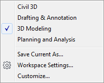
Next step is to import the GeoTIFF utilizing the mapping workspace within Civil 3D known as “Planning and Analysis”.
Planning and Analysis Workspace

Continue with this tip to finish your task….
3. AutoCAD Civil 3D Tip: Improve Performance and Speed of Civil 3D
Civil 3D drawings can often times become quite large and data intensive. Any increase in performance of handling and displaying this data is a welcome sight. One major slow-down in performance can be regeneration time when switching between Layout and Model tabs.
Here is a tip to help speed up regeneration when switching between tabs:
Continue reading for the details…
4. MicroStation Tip: Useful Keyboard Shortcut
ACCUDRAW
With the focus in the AccuDraw Dialog box there are some useful keys for changing the active snap mode.
– I (Intersection Snap)
– N (Nearest Snap)
– C (Center Snap)
– K (Keypoint Snap)
In the entry fields (X,Y,Z) for AccuDraw you can get previous entered values with Page Up/Page Down. This can be a time saver for retyping those long bearings.
– Page Up (Previous keyed in value)
– Page Down (First keyed in value)
5. MicroStation Tip: Manage Font Utilities
To add a font to a Resource file (*.rsc),:
1. Open the Keyin dialog box – Utilities > Key-in
2. Mdl load fontutilities > enter
3. Font utilities dialog > enter

This is the new dialog box that opens to allow resource file creation or modification.
6. AutoCAD Civil 3D New Feature: Extract Corridor Solid
When you create AutoCAD Solids, the program also creates shapes and links that match the way the corridor is constructed. AutoCAD solids can be used to graphically represent the mass of a subassembly shape and can be used to extract mass properties, such as volume. Solids are also more generally accepted by other solid modeling applications. Solids can also be used for rendering in other visualization applications.
1. Open a corridor file.
2. In the Toolspace, click Toolbox Tab > Miscellaneous Utilities > Corridor Solids > “Extract Corridor Solids”

7. MicroStation Tip: Civil 3D Content for MicroStation Visualization
I am often asked, “Where do you get 3D MicroStation Cells and other 3D content?” There are a number of free and pay for websites that I usually use but I would first recommend downloading the Civil Content for Visualization package from Bentley SELECTservices downloads under Enhancements and Updates. This content has a number of useful render ready 3D models to help you visualize your Civil projects.
Check out some content examples….
8. InRoads Tip: Place Dimensions in Roadway Designer
Continue to view the entire tip…
9. Civil 3D Tip: How to Create New Parts for Pressure Pipe Catalogs
1) Create your 3D solid of the part within the 3D Modeling workspace in Civil 3D. The commands and functions within 3D Modeling are very intuitive so becoming familiar enough with them to create piping parts should not take a great deal of time, but there will be some learning required. Autodesk Help is your friend for this.
3D Modeling Workspace
10. MicroStation Tip: Coordinate Input
Placing elements in MicroStation is usually done one of two ways: absolute coordinates or relative to an existing point. Workflows for placing those elements to absolute coordinates can be done one of two ways: using the Key-in Browser dialog or using AccuDraw’s Data Point Key-in.
Via the Key-in Browser:
Absolute Coordinates
1. Select a placement tool
2. In the key-in browser type the coordinates: “XY=1000,1000,0″
3. Hit the Enter key on the keyboard or the Run icon from the key-in browser. The element will be placed at the keyed in coordinate value.
4. Continue to use the key-in browser and the “XY=” key-in to finish placing elements/vertices/cells…
Don’t want to miss out on other great information? Subscribe to this blog or our monthly eNewsletter now! Learn More ◊ Contact us today ◊ Newsletter ◊