In the last tip, I outlined how to add pipe materials/sizes to Pressure Pipe Catalogs in Civil 3D. This is a follow-up to that tip which will outline how to create new fittings and appurtenances using 3D Modeling within Civil 3D. Again, Civil 3D only comes loaded with ductile iron piping as an option in the pressure parts catalog. Anything else will have to be paid for or created by the user. Creating new parts is a very cost-effective option if an extensive catalog is not required. Here are the steps:
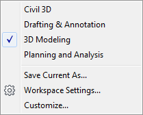
1) Create your 3D solid of the part within the 3D Modeling workspace in Civil 3D. The commands and functions within 3D Modeling are very intuitive so becoming familiar enough with them to create piping parts should not take a great deal of time, but there will be some learning required. Autodesk Help is your friend for this.
3D Modeling Workspace
2) Like with piping, it is best practice to use manufacturer specifications and dimensions when modeling the 3D solid fitting or appurtenance. This will ensure proper labeling and behavior of the part. Be sure that your drawing units are set properly before creating the part.
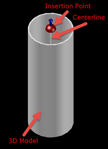
3) There are three elements required in the drawing in order for the part to be published. These are:
a. The 3D model itself. For this example, I created a simple straight coupling.
b. Insertion points for the model. These are the points at which the parts will connect to adjoining parts. Multiple insertion points will be required for parts such as a wye fitting. These will need to be created in the proper order. The first connection point of a fitting will need to be created first, and the direction will be the direction from which the part will be connecting to the adjoining part. The command for creating insertion points is AUTODESKCONNECTIONPOINT. The command prompts will go through location and direction for each insertion point.
c. A centerline for the part. This will be used by the style in order to display the centerline of the part. This can be created using 3D polylines. Multiple centerlines will need to be made for parts such as a wye fitting, and these should be made into a block to create a single entity. Insertion point and name of the block are irrelevant.
3 elements required to publish a part
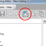
4) Once the three elements have been created, the part can now be published. This will create the .CONTENT file which can then be imported into a parts catalog through Content Catalog. Prior to publishing the part, it is good practice to make your drawing area square so the image preview of the part within the catalog is not distorted. Set the view of the part to an isometric view for an effective display of the image of the part.
5) Type the command PUBLISHPARTCONTENT to publish the part. This command will take the user through prompts to specify the solid to publish, the centerline of the solid, the units, and where to save the .CONTENT file. The new part has now been created, and can be imported into a parts catalog through Content Catalog Editor (please see my first article on adding pressure pipe parts to catalogs for instructions on doing this).
Last Month’s Tips:
MicroStation: V8i SS3 InRoads: Import AutoCAD Civil 3D 2014: VBA: Get Current Value

w/ Google Earth and … Graphics to Create … How to Add New Pipes … of all Your Var…
Don’t want to miss out on other great information? Subscribe to this blog or our monthly eNewsletter now! Learn More ◊ Contact us today ◊ Newsletter ◊
I created the custom part-5.625 degree bend. when i insert the bend in my plan view in fitting properties why the resultant horizontal angle is 0 not 5.625 degree.
can you help me with this?