Here is a quick way to add utilities and Right-of-Way info to already created section views.
Crossing objects and projected objects must be of the types: AutoCAD points, solids, blocks, multi-view blocks, 3D polylines, cogo points, feature lines, and survey figures.
In this example, I will add ROW markers to my section views.
1. Ribbon >> Home tab >> Create Design Panel >> Section Views >> Project Objects To Multiple Section Views
2. Select a section view group.
3. The Project Objects To Multiple Section Views dialog will appear.
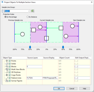
4. The graphic at the top represents the distance in front of the sample line and the distance behind the sample line that is to be included when searching for objects to project. This value can be set by percentage or by distance. (Crossing objects are automatically included if they cross the sample line.)
5. Below are 5 columns used to sort what objects are projected onto the section view.
6. The Object Type column contains the types of objects to be included in the projection. Check or uncheck objects types as needed.
7. The Source Layers column is used to include/exclude object types by layer. Click in the box to include/exclude individual object layers as needed.
8. The Source Display Column allows to filter object types by Civil 3D style. Click in the box to include/exclude individual styles as needed.
9. The Object Count column lists the number of objects that will display on the section view when projected. This is handy to determine if the correct number of objects are being selected or even just to know if there are any object types at all.
10. The Edit Output Display column is used to define the display of the objects when projected on the section view. Click in this box to bring up the next dialog box.
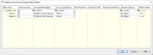
11. The Projection and Crossing Output Display Options dialog is used to set the display of projected objects.
12. In the Draw Crossings column check/uncheck items to further filter what objects will be projected.
13. Select a Crossing Marker Style that will be the visual display in the section view.
14. Select a Crossing Label Style to include in the section view. (optional)
15. In the Draw Projections column check/uncheck items to further filter what objects will be projected.
16. Select a Projection Style that will be the visual display in the section view.
17. Select a Projection Label Style to include in the section view. (optional)
18. In the Elevation Options column select where the marker/label should be placed in the section relative to elevation.
19. The Elevation Value column will then populate with the actual elevation value where the marker/label will be placed.
20. Click OK to close the dialog box.
21. Click OK to close the next dialog box.
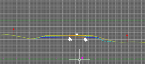
22. The section views will now show the projected items.