New in OpenRoads Deisgner CONNECT Edition is the command “Create 3D Cut”. 3D Cut creates a dynamic cut or slice of the 3D model that follows the profile and displays it in the Dynamic Profile View. Not only is this a quick way to see design elements that cross the roadway such as drainage structures, but it’s also dynamic and will update as changes are made to the model. Once the 3D Cut has been created, the elements shown in the profile view will also be shown on the profile sheet and can be annotated as well. Let’s take a look at how to create a 3D cut.
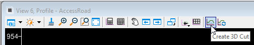
Open the Dynamic Profile View In the design file that contains your alignment and profile. The corridor can either be located in this dgn file or referenced. On the toolbar in the profile view, click on the Create 3D Cut icon.
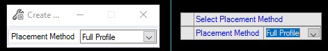
From Tool Settings and the Heads-Up Prompt, you will be prompted to select a placement method of either Full Profile or Corners. Full Profile creates a cut along the entire length of the profile, and Corners allows you to select an area with a box in the profile view to create the cut.
For this example, I used Full Profile. Click in the profile view, and the 3D Cut is created.
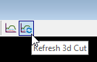
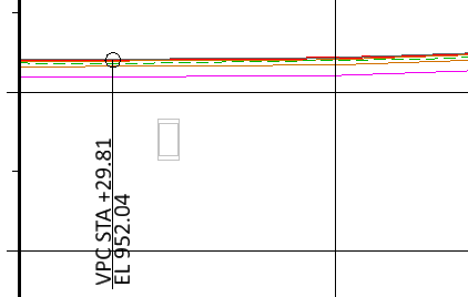
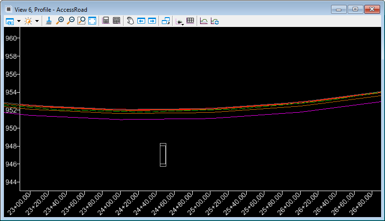 We see that a drainage structure is shown as well as the template components, so our roadway will also show an accurate depth of pavement. Any 3D design element that crosses the profile will be displayed in the profile view using the 3D Cut command. As mentioned previously, this is dynamic. For example, if you have a reference containing all of your underground utilities in a 3D file, that dgn can be attached, and the 3D cut can be updated by simply clicking on the Refresh 3D Cut icon on the toolbar. Then those elements would be shown in the profile view.
The 3D Cut can be deleted from the Dynamic Profile View by doing a Fit All and selecting the dashed boundary that represents the 3D Cut. From the heads-up prompt, select the Delete icon.
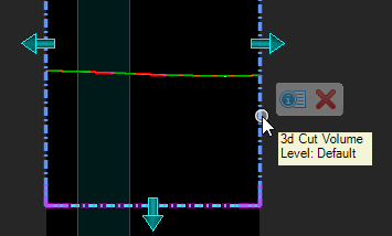
The 3D Cut boundary can also be resized horizontally and vertically by using the arrows to dynamically change the size.
After creating plan and profile sheets using Place Named Boundary, the 3D Cut will be shown on the plan and profile sheets, and since it’s dynamic, any changes made to the model will be reflected in the sheets.
Can the resulting template components display be turned OFF in the 3D Cut? I want to see the crossing culvert, but not the pavement structure.
Yes, you can turn off the level the template components are on, however that has to be done in the 3d model since what we see in the profile is just a visualization of the model. Just open the 3d model, and turn off the level of the template components you don’t want to see. Then go to the profile, and click Refresh 3d Cut.