The analytic capabilities available to drainage designers in the Drainage and Utilities toolset within OpenRoads Designer provide valuable tools for the design of drainage facilities to manage storm water runoff. The design functionally provides users assistance in system sizing of conveyance conduits within a series of user defined constraints. While this provides great automation to the process, there are often limitations to meeting those constraints. Additionally, not all the regulatory requirements needed are included in the available constraints. Designers retain the responsibility to fully validate their designs.
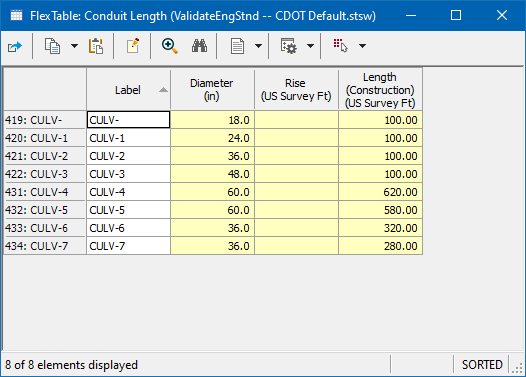
OpenRoads Designer’s Drainage and Utilities functionality provides several ways in which these requirements can be confirmed. Flex Tables can be configured to show pertinent information in tabular form to allow the designer to check the design, evaluating conduit length against the diameter or rise of a conduit.
For a more automated process, queries can be configured to locate elements that meet certain requirements. For example, the DOT limits conduits of 48″ diameter or less to a maximum 300′ length, while larger conduits can be up to 600′ in length. When activated, the query will select all the elements in the active model that meet the given criteria. See the example below with a 36″ conduit that is 320′ in length, which is over the requirement.
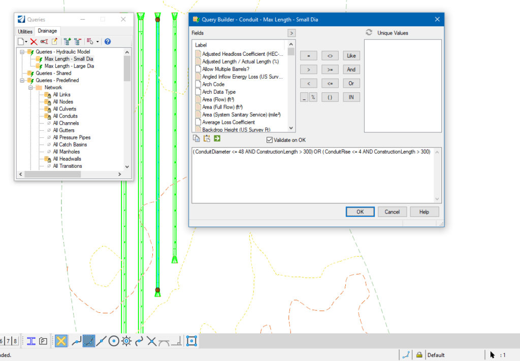
While useful, queries are somewhat limited in that a separate query would likely be needed for each validation, and each would be run separately.
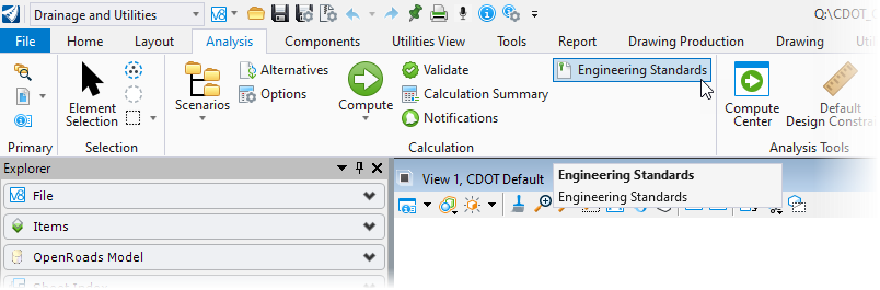
ORD provides another means of verification with Engineering Standards. This can be viewed as essentially a batch process to evaluate numerous queries simultaneously. Available on the Drainage and Utilities workflow on the ribbon (Analysis > Calculation > Engineering Standards), these can be pre-populated when a drainage and utility project is created, created locally in a file, or imported from a previously exported .DSTX file.
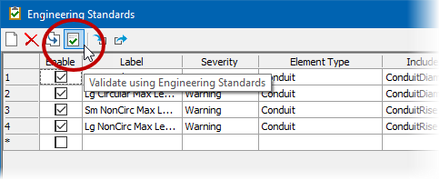
Configuring Engineering Standards is as simple as populating the columns once the dialog has been opened.
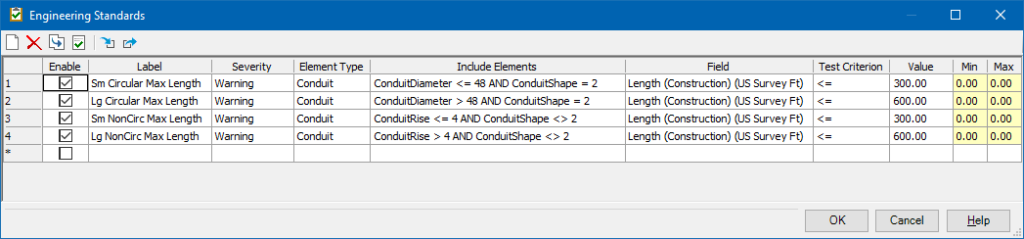
- Enable – Provides the user the opportunity to select only the validations they are currently interested in performing.
- Label – The name of the validation for user reference within this dialog. It is also included as the “Source” for notifications after the validation has been performed.
- Severity – Defines how the following test is presented, includes: Information, Warning, and Error. Each will generate a different glyph/icon in the notifications once validated.
- Element Type – Defines the type of element that will be evaluated. This also dictates the available properties that will be available to use in the Include Elements and Field columns for the test.
- Include Elements – Allows the user to limit the test to be preformed to a subset of the Element Type. This gives the user the opportunity to test a single Field against various criteria.
- Field – This is the actual property that will be compared against the Value column using the specified Test Criterion.
- Test Criterion – Defines the test that is performed. Options here are the various permutations of greater/less than and equal/not equal as well as range. It is worth noting that while these are mathematical operations nearly all properties available in the Field column do have a numerical identifier, Inlet Location for example are On Grade (0) and In Sag (1).
- Value – The value the Test Criterion is evaluated against for all criterion except Range.
- Min/Max – Define the Range evaluated against the Range Criterion.
With regards to the application of criterion in the Engineering Standards, we are trying to determine whether there are any conduits 48″ or smaller whose length is longer than 300′. In the query, we effectively coded this question so that a “true” evaluation returned the desired result. While we are looking for the same answer in Engineering Standards, we are validating a property, so a “true” statement is one that meets the desired criteria and we want to flag elements that do not meet the criteria coded. We will use the less than or equal to (<=) criterion for our Length (Construction) field in the Engineering Standards dialog.
To validate a model against the Engineering Standards, the designer simply enables the desired tests and selects the Validate using Engineering Standards icon in the Engineering Standards dialog.
Results from the evaluation can be seen in the Notifications found on the ribbon at Analysis > Calculation > Notifications on the Engineering Standards tab.
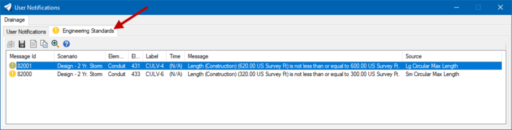
Note: One limitation of this Engineering Standards workflow is that when a single test is violated by multiple elements, only one message is generated. This will likely result in using either the Flex Tables or Queries discussed above to assist in resolving any issues.