You need to generate linear features which mark the limits of cut and fill slopes on each side of the corridor. You also need the symbology of the cut slope limits to be different than the symbology of the fill slope limits.
The solution lies in properly defined feature definitions working together with properly defined templates.
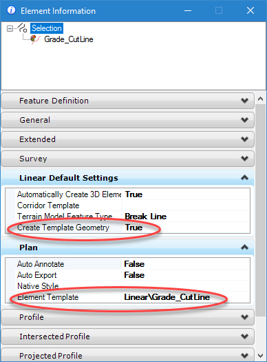
First, you need separate feature definitions for the cut and fill daylight lines. For my example, I have a feature definition named Grade_CutLine for the limits of cut slopes

And I have a Feature named Grade_FillLine for the limits of fill slopes.

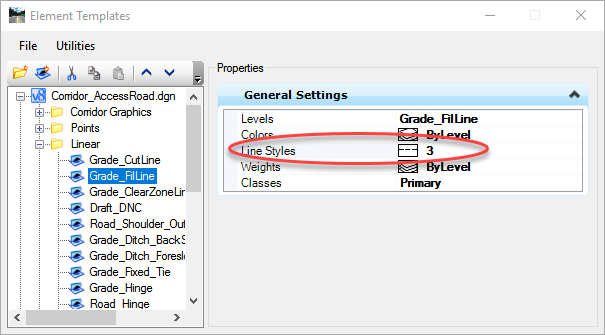
Since there are separate feature definitions then separate element templates can be used. Notice that the line style is different, solid lines for cut and dashed lines for fill. Note that if separate levels are being used, as also seen here, then bylevel for line style can also be used.
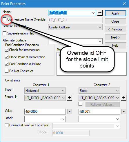
With appropriate feature definitions, then the templates need to be configured to use them. For each point at the top of cut slope or bottom of fill slope assign the appropriate feature defintion.

Then, for each of the points (top of cut and bottom of fill) you need to turn off the feature name override. With this checkbox turned on, the corridors will compute and draw a smooth transition between the cut and fill lines when the slope reverses. The problem is that with this checkbox turned on, whichever is first encountered (cut or fill) will define the symbology for the entire corridor.
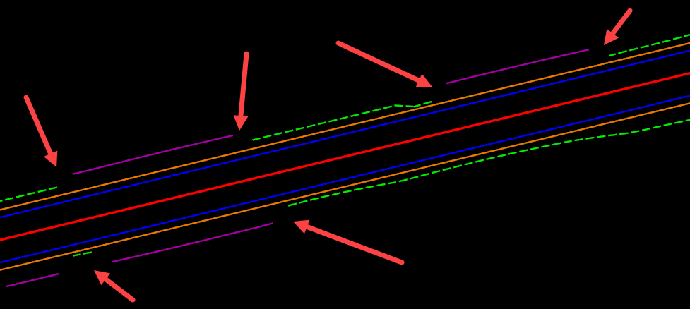
The result from the corridor will be separate symbology for top of cut and toe of fill. However, since we turned off the feature name override we will need to clean up the transitions between cut and fill ourselves.
useful information