Section Views and Sheet Layout
Move section views between section view groups:
- The section views that you want to move and the destination section view group must share the same sample line group.
- Section views can be moved from the individual section views collection to a section view group, or from one section view group to another section view group.
- The section views are inserted into the section view group in order of their stationing. They are inserted between existing section views in the group as needed so all the section views are in order.
- If the styles are different, the section views you are moving can keep their existing styles, or they can use the style of the destination section view group.
In the following example, an individual section SL-25 needs to be moved into the section view group. Its station is 1+75 so it will be inserted between the sections for station 1+50 and 2+00.
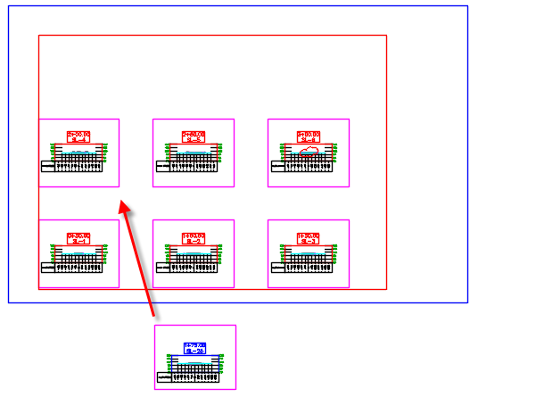
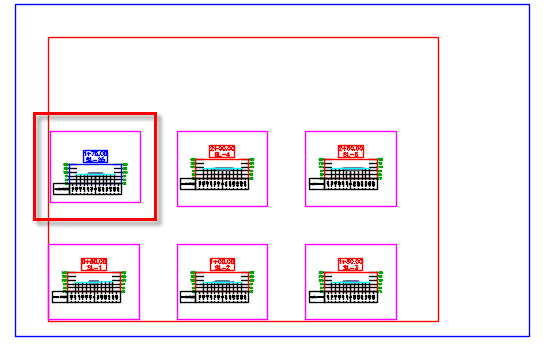
The following illustration shows the section view inserted into the section view group. You can choose to keep the existing stylization, as shown in this example, or you can choose to apply the stylization of the destination section view group to the moved sections. The section view for station 3+00 was moved to the next sheet.
Update the Sheet Layout
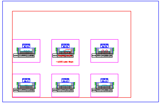
When updating the section view sheet layout, resized or inserted section views are respected. You can update the layout of a section view group to reset the location of section views that were moved out of place, or to update the layout due to another change, such as a change in a style or the change in the size of a section or of a drafting buffer. For example, in the following illustration, the bottom edge of the drafting buffer of the top-middle section was increased to accommodate the additional annotation below the section view.
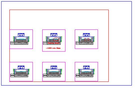
You can run the Update Group Layout command to reset the layout so that the minimum row height is applied to the layout, as follows.
Select a section view whose group layout needs to be updated.
Click Section tab>Modify View panel>Update Group Layout > Find.
The layout of the section view group is updated to reflect any changes.
Section View Drafting
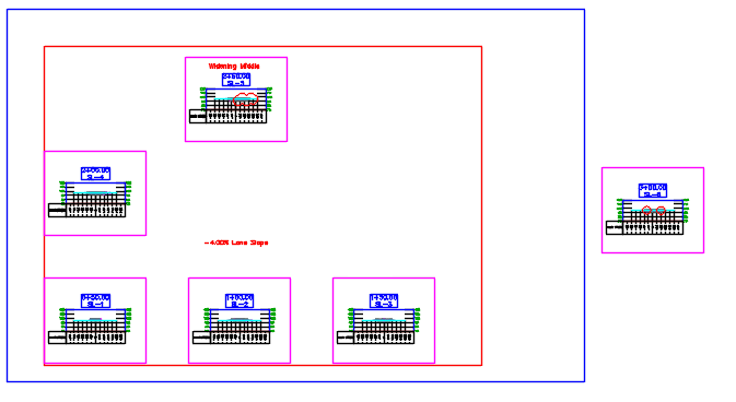
Manage section view annotation by adding it within or crossing the section view drafting buffers. Annotation and drafting elements that you add within or crossing the section view drafting buffers will be bound to the section views and will move along with the section views. Section views are created with drafting buffers. When you add AutoCAD annotation or drafting elements or AutoCAD Civil 3D note labels within or crossing the drafting buffers, they are bound with the section views and are moved with the section views if they are moved. In the following illustration, the drafting buffers around the section views are shown in magenta. Drafting elements that were added to the sheet are shown in red.
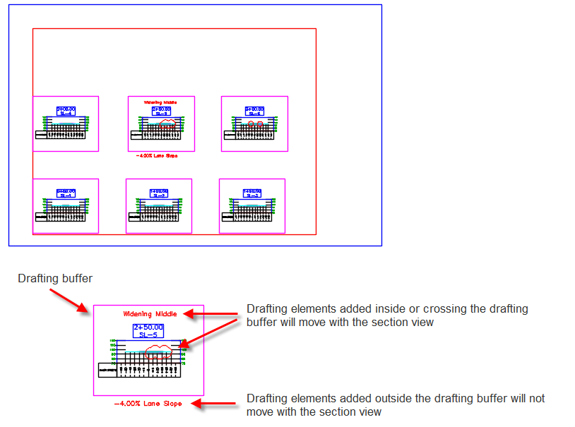
When the section views for station 2+50 and 3+00 are moved up or off the sheet, the drafting elements that are inside the drafting buffers are moved with the section views. The text that notes the lane slope is not moved because it was outside the drafting buffer area.
Binding Drafting Elements with a Section View
- Drafting elements become bound to a section view when they are added or modified within or crossing the drafting buffer.
- Any new or existing drafting elements that are added or moved within or crossing a drafting buffer become bound to the section view.
- If you make a drafting buffer larger to encompass or cross existing drafting elements, those drafting elements become bound to the section view after you make an edit to them.
- If you make a drafting buffer smaller, drafting elements that were previously inside or crossing the drafting buffer remain bound to the section view until you make an edit to them.
Drafting Buffer Grips
You can use the grips on a drafting buffer to increase or decrease its size. The following illustration shows the grips and the value of the right drafting buffer margin (50.0000) when you hover over that grip. You can select the grip and drag it to resize the drafting buffer, or you can and enter a new value at the command line.
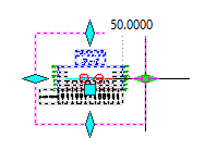
Resizing a drafting buffer after drafting elements already exist does not automatically change the binding behavior of the drafting elements relative to that drafting buffer. For more information about the binding behavior, see “Binding drafting elements with a section view” above.
Plan/Plan and Profile/Profile Sheets
Create plan/plan and profile/profile sheets by including multiple plan or profile views on a single sheet. New drawing templates have been provided that have their viewports already configured for these sheet layout types, which you can select when laying out the view frames.
New Drawing Templates
The following drawing templates have been added to accommodate the ability to create plan/plan and profile/profile sheets in AutoCAD Civil 3D 2018. The four new templates are based on the existing templates Civil 3D (Imperial) Plan and Profile.dwt and Civil 3D (Metric) Plan and Profile.dwt.:
o Civil 3D (Imperial) Plan over Plan.dwt
o Civil 3D (Metric) Plan over Plan.dwt
o Civil 3D (Imperial) Profile over Profile.dwt
o Civil 3D (Metric) Profile over Profile.dwt
Updates to Drawing Templates
The following imperial and metric NCS templates have been updated to add settings and styles to accommodate new functionality in AutoCAD Civil 3D 2018.
o _AutoCAD Civil 3D (Imperial) NCS.dwt
o _AutoCAD Civil 3D (Metric) NCS.dwt