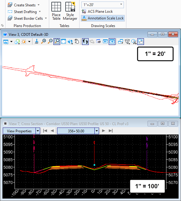
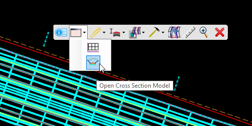
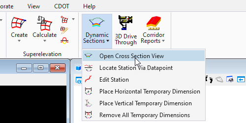
A primary advantage of using model-centric workflows such as those found in OpenRoads Designer is the opportunity for near instant feedback to design model changes. For cross section elements, this feedback is presented in the Dynamic Cross Section View available on the Corridor Context toolbar at Corridor Views > Open Cross Section Model or from the ribbon on the OpenRoads Modeling workflow at Corridors > Review > Dynamic Ssections > Open Cross Section View.
May environments are configured to show additional information in this view for corridor elements to add additional context to the dynamic cross section view. This functionality is configured on the Feature Definitions applied to the various corridor points.
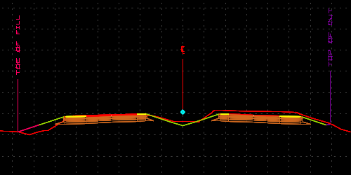
Controlling the display of these elements becomes a little tricky depending on the make-up of the view’s file and the corresponding configuration used. Understanding that this annotation is tied to the elements comprising the corridor provides some insight to help understand this functionality.
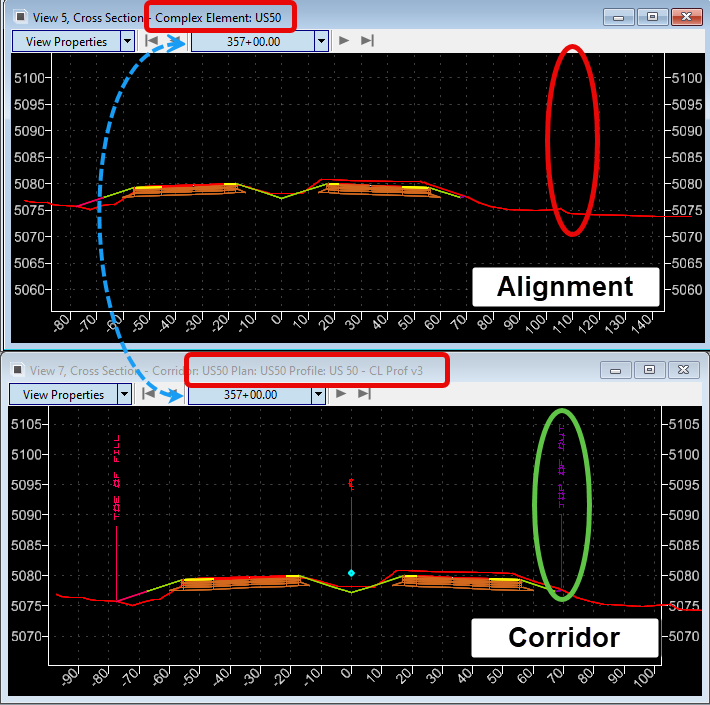
The Crossing Point annotation is only available when the cross section view is sourced from a corridor. This will always be the case when opened from the corridor context toolbar, but will need to be specifically chosen if the tool is initiated from the ribbon where any alignment can be used to define the cross section view.
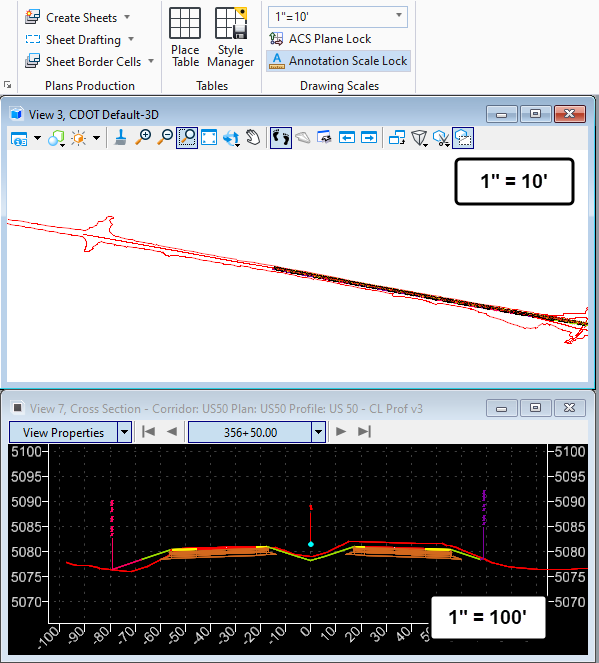
A second consideration in the display of these flags in most ORD configurations will be the assigned Drawing or Annotation Scale. This annotation is also driven by the corridor object itself, not the cut section used to display the dynamic cross section view for users. The implication here is that changes to the active view’s drawing scale do not impact the display of these flags, but changes in the 3D model drawing scale will. This applies to referenced content as well. Where the corridor resides on the drawing scale of the 3D model will control the display in the cross section regardless of what file the view is opened in.
Source 3D Model 1″ = 10′
Source 3D Model 1″ = 20′