Written by: Robert Garrett
I often get the question: How do I make alignment B exactly match the stationing of alignment A? Invariably, this question is related to special ditches, whereby the desire is to have the ditch stationing match the center-line stationing.
The answer: This is mathematically impossible unless the two alignments are both straight lines and exactly parallel.
The the followup question is: Why? My old software let me do this.
Thus the complete answer is equal parts history lesson and learning a new workflow. Consider a traditional GEOPAK special ditch profile design. (InRoads will be the same in concept.)
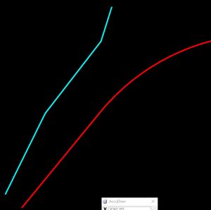
We have two alignments (center-line is red and ditch is cyan colored)

They both start at 0+00 and the start of the ditch is exactly 55ft left of the beginning of the center-line. However, they are not parallel. Therefore, by the time we get to the end of the ditch (station 5+09) the station along the center-line is only 4+48. However, in Profile, we routinely defined the ditch profile using the same stationing as exists on the center-line and ignored the difference in stationing.

We did this being mostly unaware of two underlying assumptions: 1) There may be local variations in the ditch profile which could result in a non-draining ditch. 2) If such variations exist the construction team will make appropriate grading adjustments. As I said, mostly we were unaware of these assumptions because they had been a standard part of design workflow for decades. But even if we had known, we wouldn’t have cared because we were designing by cross-sections which comprise only 2%-4% of the total surface. Our entire design was based on the same assumptions. We designed a cross-section every 50 feet based on the assumption that the contractor and design team would interpret our implied intent and grade the other 49 feet appropriately.
So, what’s different now? Automated Machine Guidance (AMG) is different. AMG allows huge gains in efficiency in construction by automating the construction equipment. The equipment has computers, GPS equipment and our model which is used to automate the cutting blades and guide the equipment operator. Because of this it is important that we provide as much detail into the model as is practical since the AMG processes will follow whatever model we provide. Of course, the equipment operator can still over-ride the model but doing so eats away at efficiency gains.
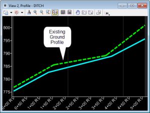
So, what does this mean to ditch profiles? Well, those minor variations in the ditch profile which are required for positive drainage must be designed in our model, which means that the ditch alignment must have its own profile space instead of using the center-line profile space. To accomplish this we open a profile view for the ditch where we likely will need to do a much more elaborate profile design that we would with the historic profile.

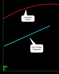
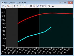
Once we get to the end of the design phase we can still produce plans with a projected profile by open the center-line profile view and using the Project Profile Command

