Here is a rather simple Civil 3D work flow to create a dynamic elevation location of a culvert pipe crown daylight (See Figure below) from an existing surface or a corridor surface.
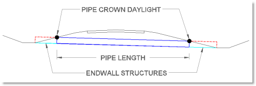
Here is how it works.
An existing or proposed surface should already be created.
In plan, create an alignment at the culvert location
- Note: Set the ends of the alignment to the end locations of the culvert Endwall structures (i.e. Flared End Structure).
Create a profile with the Create Surface Profile tool using the alignment just created.
- Note: There is no need to create a Profile View. Verify you are using the appropriate existing or proposed surface.
We will be creating two Feature lines in the same vertical plane, so we will need to create two Sites. I name one site Catch, and one CulvertCrown.
Using the Create Feature lines from Alignment tool, set the Site to “Catch” and make sure the “Create dynamic link to the alignment” is checked. See Figure 1
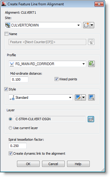
Figure 1.
This will create a Feature line that drapes across the surface at the alignment location and will dynamically update to changes made to the surface model.

Next, Create a Feature Line on the Culvert Crown site and snap to the ends of the dynamic Feature Line.
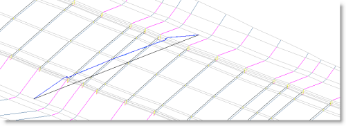
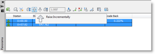
Using the Elevation editor move the end elevation of the newly created Feature Line up the diameter of the culvert pipe. Note: you may need to include the pipe thickness as well.
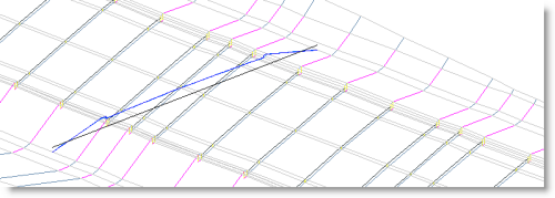
Now you can create the culvert using pipe network creation tools. Create the pipe only by snapping to the intersections of each Feature Line, which now represents the daylight pipe crown location.
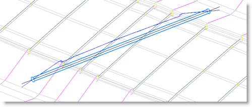
Since the pipe grip is the center of the pipe, go into the pipe properties and change the start and end crown elevations so they reflect the centerline elevations. The pipe endwall structures can be attached to each pipe end or a null structure with a pipe can be added to reflect the endwall and allow for more annotation options.
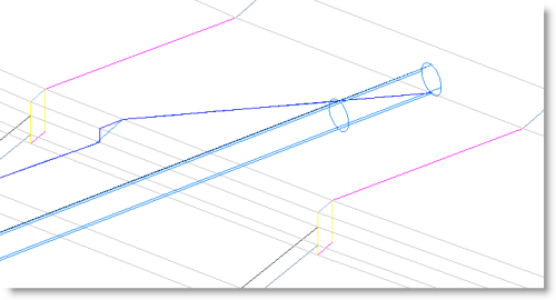
This is one way of maintaining a dynamic snap point to adjust the culvert and endwall flow locations so they match the changes with the design model.

I didn’t know that piping was so data-heavy. I need to get some new compressors for my pipes. I’ll have to order them online.