Written by Robert Garrett
In a roadway with a center barrier, we often use storm drain inlets like this one.
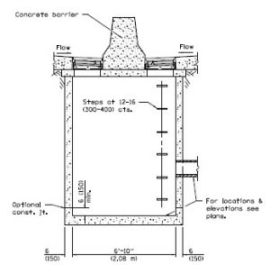
This type of structure presents a unique challenge for producing a 3D model representing the total structure while also allowing surface flow calculations independently for each grate. Additionally, the elevations of the two grates could be different as shown here. And on the high side of superelevation, there may be only one of the grates present.
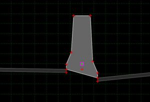
To solve this challenge we create two different feature definitions. The first feature definition is always used and is defined with a single grate, which in the library under development here is always on the low side.
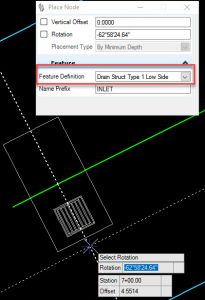
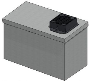
Then we configure a second feature definition which defines the other grate.
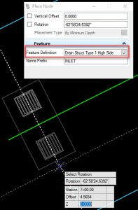
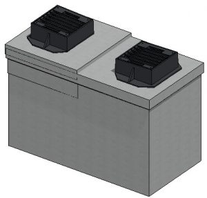
This creates for us a workable (although not perfect) 3D model. You will notice that the high side grate has only a minimal vault. In fact, the vault could be modeled as nearly nothing. Since we have two independent grates then we can also perform surface runoff and grate capacity calculations for each grate independently.
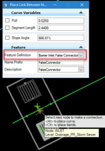
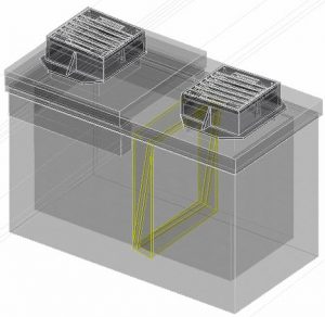
The final bit we need to account for is to make sure that the water captured by the high side grate is accounted for hydraulically in the network. We do this by setting up a false pipe which connects the high side grate to the low side grate and thus add the high side captured flow to the drainage network. The false pipe is seen in yellow, is placed in a scratch level and is made as large as possible to eliminate hydraulic effects which could occur if we made this pipe very small.
If you liked that solution to this unique challenge and you have your own structure challenges Contact Us to see how we can help you.
