Written by Ben Johnson
Alignments, like other Civil 3D objects, cannot be directly exported to shapefiles, but instead need to first be converted to AutoCAD objects. Making this conversion without losing important attribute data within the alignment is key.
The first step in getting alignments into shapefile format is to check the drawing to be sure that the proper coordinate system is set in the drawing settings. Check this by looking in the lower right corner of the program near the drawing status bar.

If there is no box showing a coordinate system then there is not a coordinate system assigned to that drawing, and this will need to be set. Set the drawing coordinate system by clicking on the Settings tab of the Toolspace, and then right-clicking on the drawing title and picking Edit Drawing Settings. In the Units and Zone tab of the Drawing Settings dialog box choose the proper coordinate system from the drop-down list, and the click Apply and OK to exit the dialog box. Save the drawing once this is done.
Civil 3D objects, such as alignments, must be exported to Autodesk Spatial Data Format (SDF) in order to convert them to data objects (polylines) and allow attributes to be associated with those data objects such as design speed and stationing. Alignments can be converted to polylines in other ways in order to create shapefiles, but none of these methods will include the alignment attributes other than exporting to SDF. On the Output tab of the ribbon choose Export Civil Objects to SDF. A dialog box will appear. Set the file name and location, and confirm that the coordinate system information is correct, and then click OK. All Civil 3D objects will then be exported to SDF. The next step is to start a new drawing, and import the newly-created SDF file. To do this type MAPIMPORT in the command line, and navigate to the SDF file. Click OK. When the Import dialog box appears, uncheck all but the Alignments in the Input Layer column. Next, click on the data column for Alignments.
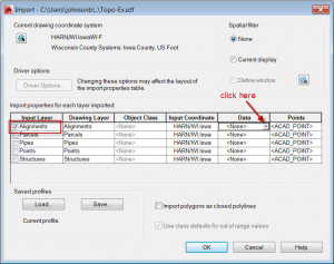
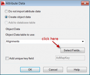
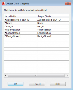
Next, click on Create object data in the Attribute Data dialog box then click on the Select Fields box. You’ll see a list of all attributes associated with the alignments in the Object Data Mapping dialog box. You can select or deselect any of these depending on which you’d like to include as attribute data in your shapefile. Click OK on all open dialog boxes to import the SDF linework.
You will now see all of the alignments in the new drawing as polylines. In order to export these to shapefiles, type MAPEXPORT in the command line. This will bring up an Export Location dialog box. Enter a file name, and choose the file type of ESRI Shapefile (*.shp), and then click OK. A new dialog box will appear. Select Line as the Object type, and choose either Select all to include all alignments in the shapefile, or choose Select manually from the Select objects to export option. To select alignments manually click the selection button, and then select only those alignments in model space you want to include in the shapefile.
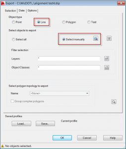
When that is done, click OK, and the shapefile will be created, complete with attribute data, for use with GIS applications.
Last month’s tips:
Don’t want to miss out on other great information? Subscribe to this blog or our monthly eNewsletter now! Learn More ◊ Contact us today ◊ Newsletter ◊

