Written by Ben Johnson
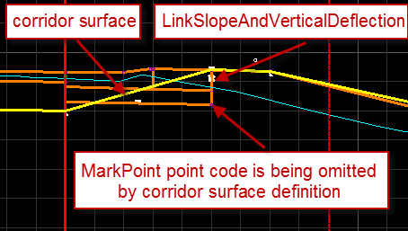
One handy use for the generic Autodesk subassembly MarkPoint is to effectively code an uncoded point on an already composed subassembly such as the UrbanCurbGutterGeneral subassembly. The UrbanCurbGutterGeneral subassembly has link codes defined for its subbase shape, but none of the subbase points are coded. Adding the feature line data for these points to a corridor surface is not possible without point codes for those points. This is where the MarkPoint subassembly comes in. MarkPoint can be added to an assembly right on top of those uncoded points, coded anyway a user chooses, and then used to add the feature lines at those points to a corridor surface. The trick of getting this to work, however, is the construction order of when the MarkPoint subassembly is added to the assembly in relation to other subassemblies in that assembly group. For instance, if an assembly is already completely constructed, and MarkPoint is added on at the end, the order will be wrong and its point code will not be added to the corridor surface definition. This is because the surface definition will have added the point code data in the order they appear in the assembly group construction order rather than in the order they physically appear moving from the baseline outward toward the roadway daylight. This results in the MarkPoint subassembly point code being omitted, even when that feature line code is added in the corridor surface definition.
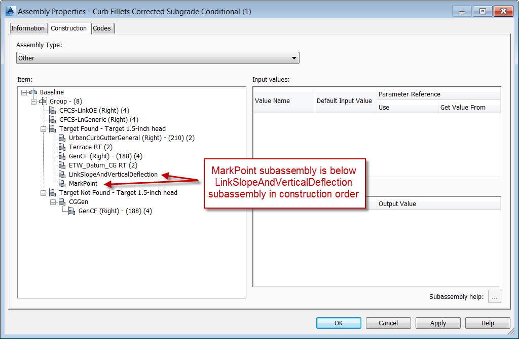
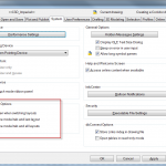
Dialog Showing Incorrect Construction Order of MarkPoint Subassembly Relating to LinkSlopeAndVerticalDeflection Subassembly
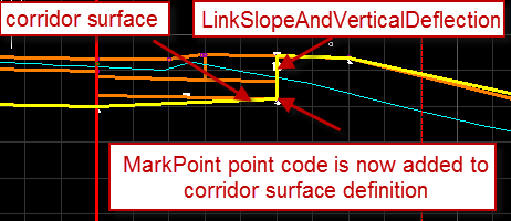
Unfortunately, the construction order of the subassemblies within an assembly group cannot be rearranged in the Assembly Properties dialog box like assembly groups themselves can be. A tip to avoid deleting and re-constructing the subassemblies in the proper order is to move all of the subassemblies which should be below MarkPoint in construction order to a different marker point on the assembly, and then move them back again. Any subassembly which is moved is automatically set to the bottom of the construction order. In the above illustrated example, only the LinkSlopeAndVerticalDeflection subassembly needs to be moved. To do this, one would right-click on the LinkSlopeAndVerticalDeflection subassembly for this example, choose Move To, and then pick any other marker point within the assembly. Next, repeat that step and move it back to its original location in the assembly. This process will push that subassembly down in the construction order without having to re-place it and re-enter its parameters.
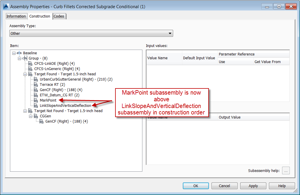
Dialog Showing Correct Construction Order of MarkPoint Subassembly Relating to LinkSlopeAndVerticalDeflection Subassembly
Again, the trick with getting the MarkPoint subassembly to work correctly is in the construction order. If it is added to an assembly last, one can re-arrange the order by physically moving the location of the other subassemblies in order to move them down in the order. This will avoid having to re-enter subassembly parameters. Simply move them back again to the original locations, and everything should work as expected.
Last month’s tips:
 MicroStation: Key InRoads: Horizontal AutoCAD Civil 3D: VBA: Message Box
Point Snap Geometry working … Improve Performance… Buttons
Don’t want to miss out on other great information? Subscribe to this blog or our monthly eNewsletter now!
Learn More ◊ Contact us today ◊ Newsletter ◊

Great tip!