InRoads Tip: Place Coordinate Grid

Written by Bob Mecham.

Use the Place Coordinate Grid tool in InRoads to layout simple grid lines or points.

1. Place either a MicroStation Shape or Fence in the file to define the boundary of the grid placement.

2. From the InRoads menu, go to the Drafting > Place Coordinate Grid.

3. This will give you a grid tick or line and label as defined. See the far right column in the dialog to set text attributes including rotation and offset.

Note: Global scale factor setting will come into play for text sizes.
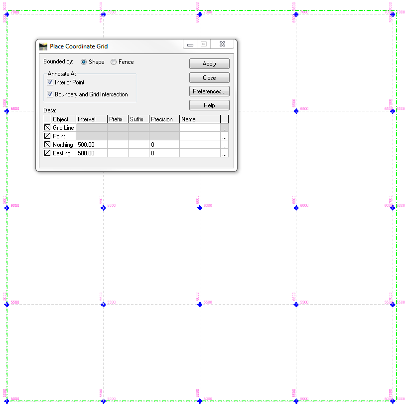
inroads place coordinate grid


Last Month’s Tips:

dialog to import linestyle library                    Element Enumerators                     SDF Import Dialog Box

MicroStation Tip:  Import Linestyles          VBA Tip:  Maximize the                Civil 3D Tip:  Converting Civil 3D Alignments
into a DGN Library                             MicroStation ElementEnumerator                 to ARCGIS Shapefiles

Don’t want to miss out on other great information? Subscribe to this blog or our monthly eNewsletter now!
Learn More ◊ Contact us today ◊ Newsletter ◊
EnvisionCAD Group EnvisionCAD YouTube Channel   

Bob Mecham

Bob is a partner at EnvisionCAD and is an industry expert in the implementation, configuration, instruction, development, and customization of both MicroStation and InRoads.

Tags:

Leave a Reply

Your email address will not be published. Required fields are marked *