Tools built using Bentley’s OpenRoad Technology include the ability to leverage drainage and utility design tools incorporated into civil products. The Subsurface Utility Design and Analysis (SUDA) functionality included with the SELECTseries 4 versions of GEOPAK, InRoads, and MXRoads and OpenRoads, OpenRail and OpenSite Designer CONNECT Editions utilize MicroStation functionality to digitally represent the “physical model” of utility networks, and integral to the 3D model is the use of cells to represent node design. To provide connectivity in the utility model between nodes and conduits, these cells include geometry defining the connection region where a conduit may connect to a node.
While this methodology provides the user with a great deal of flexibility, it has some limitations in the implementation. One of these is the inability to use MicroStation snaps to precisely place a conduit in a given location on a node, particularly problematic with end sections for storm sewers and culverts.
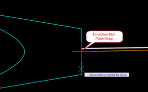
Conduit Placement with Snap
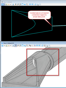
Resultant Model
The software interprets the actual data point location for the intention of the designer, effectively ignoring the snap functionality within MicroStation. In this instance, the defined connection region is centered on the alignment point of the referenced cell. Adjusting the connection region so that it is offset to one side of the alignment region provides the user an opportunity to center the conduit by selecting anywhere opposite the region when placing conduits.
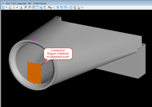
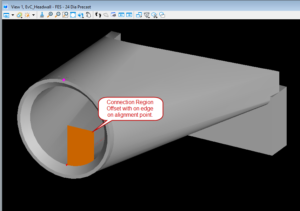
Initial and Adjusted Connection Region
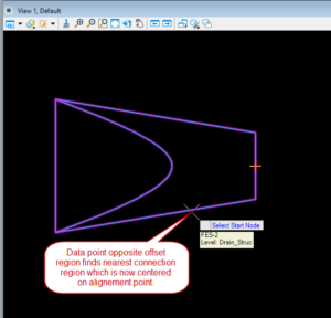
Simplified Placement of Conduit
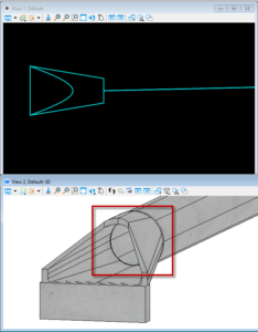
Corrected Resultant Model
A few final comments. Similar behaviors can be achieved by using a single vertical line for the connection region centered on the alignment point in the cell. This will only allow centered placement, but will not trim the conduit to the node face (as determined by the shape of the connection region), an issue if pipes are not perpendicular to the node face.
